WESTPORT TERMINAL RR |
BLT 1999
|
[How to scratch build turnouts] and [crossings] [Manual thrown Peco turnouts] [switch stands] [Movable magnets] [DCC] [beacon light] [CB&Q 173] [RS-1 and weathering] [tender pick up 0-8-0] [ Track Cleaning Transfer Caboose ] [ Signal Bridge ] [Operation] [Way of Hopper BN 25 3 84] [WT RR industries shipping & receiving] download Excel [carcards&waybills] 900kB [staging] [Harbor District] [Plywood District] [Third Street Industrial District] [track scale, structures] [Operating gates] [Waterfront Structures] [trestle] [Interchange Cars] [car exchange] [pass exchange] [electronic rail pass ] [ video ] |
How to scratchbuild crossings
Diese Seite auch auf
Deutsch. ![]()
still in work - any help and comments appreciated
Before one starts building a crossing you should have soldered
some turnouts. A crossing requires somewhat more experience.
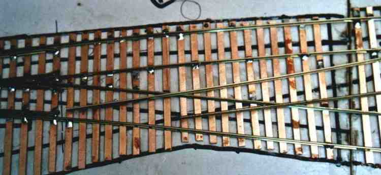
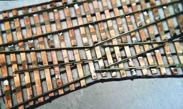
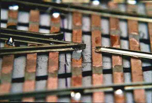
First I had soldered the two turnouts.The two branching tracks result in
the crossing. On the right at the contour the module boundary is to be detected.
No rails are still separate. All rails which run over this module boundary
must be fixed soldered before the separation.
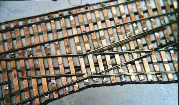
Now the from the right turnout branching rails are soldered with the NMRA gauge. The track branching from the left turnout ist soldered firmly up to the crossing already. Now the two rails can be shortened to the correct length. You must file good at the bottom of the rail so that everything fits.
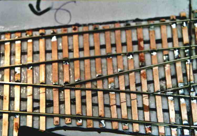
Now these rails are soldered on and the two frogs are soldered, too. Also the from the left comming rails are soldered on. Since all rails are soldered over the module boundary now these can become separated. This is to be seen.
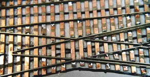
Now the from the left comming rail one out-saws. The from the right comming track serves al gauge.
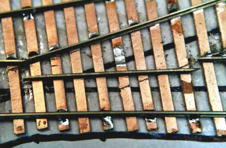
The riped out piece is filed to the correct length and soldered with the help of the NMRA gauge. Subsequently the next pice of rail can be fit in. Also here the distance to the other rail of the track is to be controlled with the NMRA gauge.
Now becomes the still remainilng rail to be separated. Again the available rail can serve as guide for the saw.
Here are inserted the first guardrails. |
top |
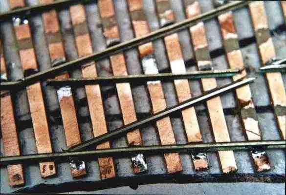
During the preparation of the frogs must be done over again with the file. And again and again check the gauge!
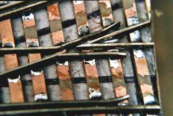
In such a way looks then the finished frog.
The attachment of all guardrails requires something patience, represents however no problem. Now the last work comes. Soldering the current feeders
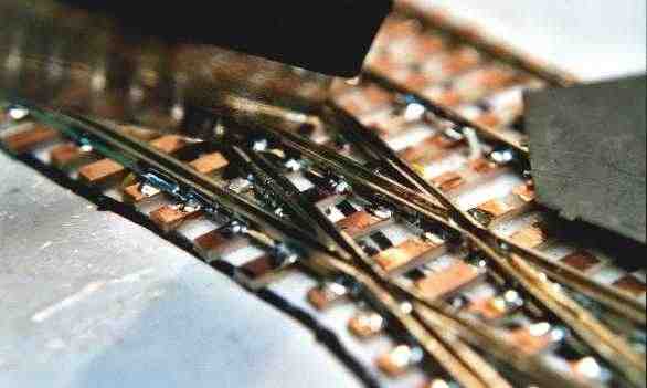
and the cutting of the rails. Here the Roco saw with its fine saw blade finds application!
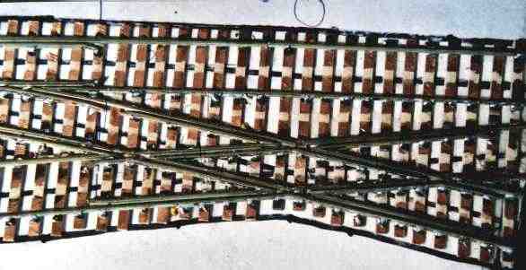
Now the crossing is ready for use. The first cars can roll over it. For the electrical supply some switches must be wired. This crossing should be wired conventionally, but for two cabs. The four frogs must be able to be supplied independently with power. The switches for this are served by the switch motor.
Another example for a curved crossing I build at Harbor District (the last picture).
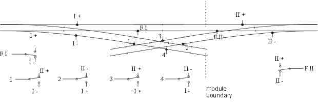
Since the right turnout on the other module is, from it only
the own frog is served. The frogs of the crossings are served from the left
turnout. If this turnout is straight, a train from the right can come. If
this turnout is on branch the crossing can be driven on from left.
I and II are the two cab areas, in each case with + and - pole.
F are the frogs of the two turnouts. 1, 2, 3 and 4 ar the four frogs of
the crossing. The switches are drawn in normal position - turnout straight!
The last crossing was build for my module Diamond Valley, you find a How To with my wiring under turnout. The left turnout powers the crossing and need therefore two DPDT switches.
And this is the DPDT switch I use for the left turnout:
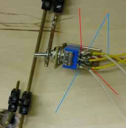
The red lines (the yellow wires) show to the contact where the power for the red rail comes. In the middle is the contact for the frog. Analog the blue lines (the white wires).
Still any questions? Write to Wolfgang Dudler
next top
| [How to scratch build turnouts] and [crossings] [Manual thrown Peco turnouts] [switch stands] [Movable magnets] [DCC] [beacon light] [CB&Q 173] [RS-1 and weathering] [tender pick up 0-8-0] [ Track Cleaning Transfer Caboose ] [ Signal Bridge ] [Operation] [Way of Hopper BN 25 3 84] [WT RR industries shipping & receiving] download Excel [carcards&waybills] 900kB [staging] [Harbor District] [Plywood District] [Third Street Industrial District] [track scale, structures] [Operating gates] [Waterfront Structures] [trestle] [Interchange Cars] [car exchange] [pass exchange] [electronic rail pass ] [ video ] |